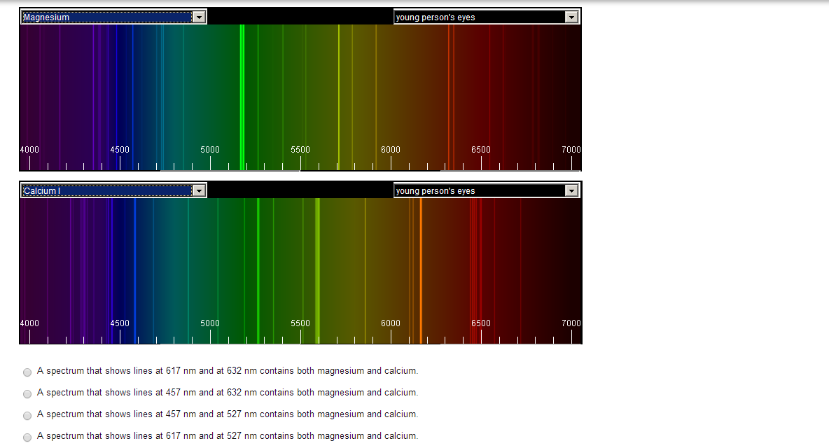

Slanger TG, Cosby PC, Huestis DL, Saiz-Lopez A, Murray BJ, OSullivan DA, Plane JMC, Prieto CA, Martin-Torres FJ, Jenniskens P (2005) J Geophys Res 110:D23302. Noll S, Kausch W, Kimeswenger S, Unterguggenberger S, Jones AM (2015) Atmos Chem Phys 15:3647. Pendleton WR Jr, Espy PJ, Hammond MR (1993) J Geophys Res 98(A7):11567. Von Savigny C (2015) J Atmos Sol Terr Phys 127:120įrench WJR, Klekociuk AR (2011) J Geophys Res 116:D00P09. Von Savigny C, Langowski M, Zilker B, Burrows JP, Fussen D, Sofieva VF (2016) Geophys Res Lett 43. Lednyts’kyy O, von Savigny C, Eichmann KU, Mlynczak MG (2015) Atmos Meas Tech 8:1021. Von Savigny C, McDade IC, Eichmann KU, Burrows JP (2012) Atmos Chem Phys 12(18):8813 doi: 10.1029/93JD00227īurrows JP, Hoelzle E, Goede APH, Visser H, Fricke W (1995) Acta Astronautica 35:445īovensmann H, Burrows JP, Buchwitz M, Frerick J, Noel S, Rozanov VV, Chance KV, Goede APH (1999) J Atmos Sci 56(2):127 An atomic emission spectrometer is similar in design to the instrumentation for atomic absorption. Offermann D, Hoffmann P, Knieling P, Koppmann R, Oberheide J, Steinbrecht W (2010) J Geophys Res 115:D18127. The inset shows a close up of the emission lines at 589.0 and 589.6 nm that appear in the energy level diagram in Figure 10.1. Slipher VM (1929) Publ Astron Soc Pac 41:262 McLennan JC, Shrum GM (1925) Proc R Soc (London) A 108:501 Khomich VY, Semenov AI, Shefov NN (2008) Springer. Picone JM, Hedin AE, Drob DP, Aikin AC (2002) J Geophys Res Space Phys 107(A12):1468. Shepherd GG, Cho YM (2017) Geophys Res Lett 44. Slanger TG, Cosby PC, Huestis DL, Bida TA (2001) Science 291:435 After the sample has dissolved, it is transferred to a 250-mL volumetric flask and diluted to volume with distilled water.Piccioni G et al (2008) Astron Astrophys 483:L29 Because it is difficult to match the matrix of the standards to that of the sample, the analysis is accomplished by the method of standard additions.Ī sample is prepared by placing an approximately 10-g portion of the salt substitute in 10 mL of 3 M HCl and 100 mL of distilled water. Typically, the concentration of sodium in a salt substitute is about 100 μg/g The exact concentration of sodium is determined by flame atomic emission. Although intended to be sodium-free, salt substitutes contain small amounts of NaCl as an impurity. Depending on the brand, fumaric acid, calcium hydrogen phosphate, or potassium tartrate also are present. 10.2 shows examples of a continuous, an emission and an absorption spectrum. This is called an absorption spectrum because the gas is absorbing light at specic wavelengths. Salt substitutes, which are used in place of table salt for individuals on low-sodium diets, replaces NaCl with KCl. the light pass through a prism you see dark lines in the continuous spectrum. The description here is based on Goodney, D. Although each method is unique, the following description of the determination of sodium in salt substitutes provides an instructive example of a typical procedure.

The best way to appreciate the theoretical and the practical details discussed in this section is to carefully examine a typical analytical method. Representative Method 10.7.1: Determination of Sodium in a Salt Substitute To accurately correct for these errors the analyte and internal standard emission lines are monitored simultaneously. In addition, the internal standard should be subject to the same chemical interferences to compensate for changes in atomization efficiency. To compensate for changes in the temperature of the excitation source, the internal standard is selected so that its emission line is close to the analyte’s emission line. The method of internal standards is used when the variations in source parameters are difficult to control. An increase in temperature of 10 K, for example, produces a 4% increase in the fraction of Na atoms in the 3 p excited state, an uncertainty in the signal that may limit the use of external standards. When using a plasma, which suffers from fewer chemical interferences, the calibration curve often is linear over four to five orders of magnitude and is not affected significantly by changes in the matrix of the standards.Įmission intensity is affected significantly by many parameters, including the temperature of the excitation source and the efficiency of atomization. \( \newcommand).Ī calibration curve for flame emission usually is linear over two to three orders of magnitude, with ionization limiting linearity when the analyte’s concentrations is small and self-absorption limiting linearity at higher concentrations of analyte.


 0 kommentar(er)
